The Critical Role of Error Vector Magnitude in Modern Wireless Communications
Introduction
In the fast-evolving landscape of wireless communications—spanning Wi-Fi, LTE, and 5G NR—the ability to transmit data reliably at high speeds hinges on signal integrity. One of the most important metrics for assessing that integrity is error vector magnitude (EVM). This article explores what EVM is, how it is calculated, why digital modulation accuracy matters, the primary causes of EVM degradation, and how engineers can diagnose problems using constellation diagrams. By understanding and mastering EVM, system designers can ensure next-generation wireless networks meet ever-increasing performance demands.

What Is Error Vector Magnitude and How Is It Calculated?
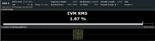
EVM quantifies the difference between an ideal (theoretical) transmitted signal and the actual received signal. In digital communication systems, symbols are mapped to specific points in a constellation diagram (e.g., QAM points). The error vector is the distance between the ideal point and the measured point on that diagram.
Peak vs. RMS Normalization
EVM can be expressed using either peak or RMS (root mean square) normalization. Peak normalization divides the error vector magnitude by the maximum amplitude of the ideal constellation point, while RMS normalization uses the average power of the constellation. The choice affects the numerical value and interpretation, but RMS is more common in standards like 3GPP and IEEE 802.11.
Percentage and Decibel Formats
EVM is reported either as a percentage (e.g., 1.5%) or in decibels (dB) (e.g., -36.5 dB). The dB scale is logarithmic and often preferred because it directly relates to signal-to-noise ratio (SNR). A lower percentage or a more negative dB value indicates higher modulation accuracy.
How Digital Modulation Works and Why It Matters
Digital modulation techniques such as ASK (Amplitude Shift Keying), FSK (Frequency Shift Keying), PSK (Phase Shift Keying), APSK (Amplitude and Phase Shift Keying), and QAM (Quadrature Amplitude Modulation) encode data by varying the amplitude, phase, or both of a carrier wave. Higher-order modulation schemes (e.g., 256-QAM, 1024-QAM) pack more bits per symbol, thereby increasing throughput.
However, more bits per symbol means constellation points are closer together, making the system extremely sensitive to noise, distortion, and other impairments. To achieve reliable transmission, the error between the actual signal and the ideal must be very small—hence the need for a stringent EVM requirement. For instance, 5G NR with 256-QAM may require EVM below about 3.5% (or -29 dB).
What Causes Degraded EVM in Real-World Systems
EVM degradation arises from multiple hardware and environmental factors. These can be grouped into four main categories:
- Amplitude Effects: Compression from power amplifiers, thermal noise, and non-flat frequency response all distort the signal amplitude.
- Phase Effects: Phase noise from local oscillators introduces random phase jitter, rotating constellation points.
- I/Q Imperfections: Gain imbalance between in-phase (I) and quadrature (Q) channels, as well as quadrature error (non-90° phase difference), cause the constellation to become skewed.
- Configuration Issues: Incorrect symbol timing, carrier frequency offset, or filter mismatches can also increase EVM.
Identifying which category is the primary culprit is essential for effective system debugging and improvement.
How to Diagnose Modulation Impairments Using Constellation Diagrams
Visual inspection of a constellation diagram is a powerful diagnostic tool. Each type of impairment leaves a characteristic signature. For example:
- Phase noise appears as a rotational spreading of constellation points around the ideal location.
- Amplifier compression compresses outer constellation points more than inner ones, creating a “squashed” appearance.
- Additive white Gaussian noise (AWGN) produces a uniform circular cloud around each point.
- In-band spurious signals cause multiple concentric rings or offset clusters.
- I/Q modulator imperfections result in elliptical or skewed constellations.
By studying these patterns, engineers can quickly pinpoint the root cause of poor EVM and take corrective action, such as adjusting amplifier bias, improving I/Q calibration, or reducing phase noise.
Conclusion
Mastering EVM is not optional for designers of next-generation wireless systems—it is essential. From understanding the basic calculation and normalization schemes to recognizing the impact of different digital modulation orders and diagnosing real-world impairments, EVM serves as the primary lens through which modulation accuracy is quantified. Armed with this knowledge, engineers can optimize transceiver performance, meet compliance standards, and deliver the high data rates that modern users expect.
Related Articles
- How to Protect Your Organization from the Latest Cyber Threats: A Step-by-Step Guide Based on the 11th May Threat Intelligence Report
- Haiku OS Makes Strides with ARM64 Multi-Core Support
- Cloudflare's Code Orange Project: A Stronger, More Resilient Network
- Building macOS Apps from Scratch: The Complete Beginner’s Guide
- Django's Explicit Design Wins Over Developers Seeking Long-Term Project Stability
- Casey Hudson’s Critique of AI in Game Development and What It Means for Star Wars: Fate of the Old Republic
- 10 Key Insights into TurboQuant: Google's Breakthrough in KV Compression for AI
- 7 Essential Practices to Turn AI Session Learnings into Team-Wide Improvements